Ansys Common Fluids Mesh Data Model
Last update: 24.03.2026Mesh Data Model
The Ansys Common Fluids Mesh Data Model is defined to store mesh and can be thought of as a discretization of geometric space into smaller Elements on which a solver may calculate a fluid simulation.
In its simplest form, a mesh is a collection of Elements that are called Cells, Faces, Edges, and Nodes.
Elements can be defined in a number of ways, depending on the type of Elements that might be needed and the Mesh Dimensionality of the Geometric space being represented.
Meshes within the Data Model are defined as collections of Elements. Elements can be categorized as Cells, Faces, Edges, and Nodes.
The Element topology of Cells, Faces, and Edges will ultimately be determined in terms of Nodes.
Mesh Dimensionality
The dimensionality of a mesh will typically be decided by the type of solver being run and the type of geometric space it works in. A mesh is typically two-dimensional (2D) or three-dimensional (3D).
The number of coordinates each Node has determines the dimensionality of the mesh. In a 3D mesh a Node will have 3 coordinates whereas a 2D mesh will have 2 coordinates.
The dimensionality of a mesh will imply what type of Cells can be stored and therefore the Faces that are also stored.
- Note
- It is important to remember that the Cells or Faces stored don't determine the dimensionality of the mesh. A Triangle, for example, can be represented as a 3D Face or a 2D Cell but the reverse isn't true, as a Triangle can only be represented as a cell within a 2D mesh.
To read or write mesh dimensionality, see the API function documentation for getMeshSize and setMeshSize.
Units
Mesh units are optionally stored with the mesh. The absence of units within a mesh should be interpretted by the CffProvider API as indicating that the mesh is in the default SI unit of meters.
To read or write mesh units, see the API function documention for getMeshUnits and setMeshUnits.
Elements
Mesh Elements are one of Cells, Faces, Edges, or Nodes.
To read or write the total number of each object, see the API function documentation for getMeshSize and setMeshSize.
The following definitions are used when referring to Cells, Faces, and Nodes:
| Mesh Dimension | Cell | Face | Node |
|---|---|---|---|
| 3D | 3D (Tet, Pyramid, Wedge, Hex, Poly) | 2D (Quad, Tri, Poly) | 0D (that is, Point) |
| 2D | 2D (Quad, Tri, Poly) | 1D (Edge) * | 0D (that is, Point) |
- Note
- The types of Cell and Face will depend on the dimension of the mesh.
Element Types
There are many types of mesh element defined.
Cells types are defined as ansys::CellType.
To read or write cell types, see CffProvider::startReadingTypesForCells and CffConsumer::startWritingTypesForCells and associated functions.
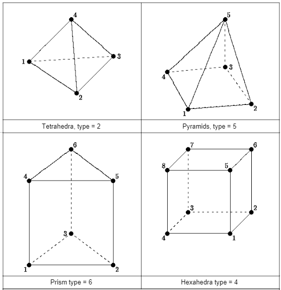
Element Topology
Non-polyhedral 3D elements must be defined using the following node orderings.
Nodes
Nodes are defined by coordinates. In a 3D mesh, the number of coordinates per node is 3. In a 2D mesh, the number of coordinates is 2.
- See also
- API functions CffProvider::startReadingCoordinatesForNodes and CffConsumer::startWritingCoordinatesForNodes.
Mesh Size
The total number of each type of Elements (Cell, Face, Edge, and Node) is available in the Data Model.
Zone
Zones are groupings of Elements of the same dimensionality. The way Elements are grouped into Zones is arbitrary. They may be grouped by a single ansys::CellType or may be grouped into a Zone of mixed type ansys::CFF_CELL_TYPE_MIXED.
There are four types of Zone available (Cell Zones, Face Zones, Edge Zones and Node Zones).
In both the CFF Restart Data Model and CFF Post Data Model there may be multiple zones of each type, however it is important to understand how the Zone Connectivity differs.
Cell Zones
The Elements are called Cells within a Cell Zone.
The Zone will have a type of ansys::CFF_CELL_ZONE.
The Cells defined within a Zone will depend on the Mesh Dimensionality
For a Mesh Dimensionality of 2 the Cells will be of one of the following types:
- ansys::CFF_CELL_TYPE_TRI
- ansys::CFF_CELL_TYPE_QUAD
- ansys::CFF_CELL_TYPE_POLY
- ansys::CFF_CELL_TYPE_GHOST (in special circumstances)
For a Mesh Dimensionality of 3 the Cells will be of one of the following types:
- ansys::CFF_CELL_TYPE_TET
- ansys::CFF_CELL_TYPE_PYRAMID
- ansys::CFF_CELL_TYPE_WEDGE
- ansys::CFF_CELL_TYPE_HEX
- ansys::CFF_CELL_TYPE_POLY
- ansys::CELL_TYPE_TET10 (in special circumstances)
Face Zones
The Elements are called Faces within a Face Zone.
The Zone will have a type of ansys::CFF_FACE_ZONE
For a Mesh Dimensionality of 2, the Faces will be of one of the following types:
For a Mesh Dimensionality of 3 the Faces will be of one of the following types:
- ansys::CFF_FACE_TYPE_TRI
- ansys::CFF_FACE_TYPE_QUAD
- ansys::CFF_FACE_TYPE_POLY
- ansys::CFF_FACE_TYPE_TRI6 (in special circumstances)
Edge Zones
An Edge Zone will only be available where the Mesh Dimensionality is 3.
The Elements are called Edges within a Edge Zone. The Edges may have either of the following typpes:
- ansys::CFF_EDGE_TYPE_LINEAR
- ansys::CFF_EDGE_TYPE_LINEAR3 (in special circumstances)
The Zone will have a type of ansys::CFF_EDGE_ZONE
Node Zones
The Elements are called Nodes within a Node Zone.
The Zone will have a type of ansys::CFF_NODE_ZONE
Zone Connectivity
The Zone Connectivity describes how one Zone is related to another. A distinction exists between the CFF Restart Data Model and CFF Post Data Model.
Zone Connectivity within a Restart Data Model
The Nodes within a Node Zones in a CFF Restart Data Model will be referenced from multiple Cell Zones and/or Face Zones. However, not all Node Zones will necessarily be referened by all Cell or Face Zones.
In a CFF Restart Data Model the Face Zones bound one or more Cell Zones. As any face within one such Face Zone within the CFF Restart Data Model will have either one or two parent cells (C0 and/or C1), the Face will share nodes with the cell.
- See also
- Cell Representation
Zone Connectivity within a Post Data Model
In the CFF Post Data Model each Zone is independent, by which we mean that no Node will be referenced by more than one Face Zone or Cell Zone. This means that there must be only one Cell Zone or Face Zone associated with any Node Zone.
- See also
- Cell Representation
Cell Representation
A cell's definition describes how cells are represented within the Ansys Common Fluids Mesh Data Model.
We use the following terminology to describe the representations of Cells: Cell/Node Definition, Face/Node Definition, and Poly/Face Definition.
- Note
- Within a CFF Restart Data Model, only Cell/Node Definition and Face/Node Definition are valid.
- Within a CFF Post Data Model, only Cell/Node Definition and Poly/Face Definition are valid.
Typically a specific CFF Restart Data Model will only represent cells using one form of connectivity. This typically leads to the whole Ansys Common Fluids Mesh Data Model being thought of as having a single type of Cell Representation. However, it is best practice to determine how each Cell Zones is represented by checking to see whether it has been represented with Cell/Node Definition by calling ansys::CffProvider::startReadingNodesForCells, which will return those Cell Zones that have Cell/Node Definition. If a Cell Zones is not in this list it will be a Face/Node Definition connectivity.
The same approach can be used with CFF Post Data Model but Cell Zones which don't have Cell/Node Definition will instead have Poly/Face Definition.
Cell/Node Definition
A Zone with Cell/Node representation defines the connectivity of the Cells using nodes.
Each Cell is well-defined and is defined by a Node Count and an associated sequence of ordered Nodes. It is important to note that Cell/Node connectivity can never be used to represent Polyhedral cells because they are not well-defined.
It is possible in a 3D case to represent the 4 basic cell types CFF_CELL_TYPE_TET, CFF_CELL_TYPE_HEX, CFF_CELL_TYPE_PYRAMID, and CFF_CELL_TYPE_WEDGE. But it is also possible to define a cell with the type CELL_TYPE_TET10 in this manner.
In a 2D case it is possible to define cells of type CFF_CELL_TYPE_TRI and CFF_CELL_TYPE_QUAD and in particular circumstances CFF_CELL_TYPE_GHOST.
If you wish to represent a Polyhedral Cell it must be done using the Face/Node Definition in a CFF Restart Data Model or the Poly/Face Definition in a CFF Post Data Model.
Face Zones Definitions where Cell Zones define a Cell/Node Definition
When a Cell Zone has been defined using Cell/Node Definition, a Face Zone typically represents some or all of the bounding faces of the Cell Zones. Interior faces that don't take part in a meaningful bounding region need not be written to an extra Face Zones, as is required by the Face/Node Definition as the Cells are well-defined. This can considerably reduce the number of Faces written to the model.
It should be noted that the way Face Zones are defined is (in general) identical to how they are represented within a Face Zone Definitions. That is, each face within a Face Zones will be defined by type, node count, node ids. Within a CFF Restart Data Model, parent cell information must always be provided, however, when writing to a CFF Post Data Model the parent cell information must be omitted.
Definition within a Restart Data Model
Within a CFF Restart Data Model Face Zones are defined in the same way as they are defined for a Face Zone Definitions and will include parent cell(s) references.
- Note
- It is important to note that the node ids will be common in numbering with the parent cell.
Definition within a Post Data Model
Within a CFF Post Data Model, Face Zones are again defined in the same way as Face Zone Definitions but there will be no parent cell references (C0 and C1) data as the Zones will not share the same nodes: they must be defined using independent Node Zones.
Face/Node Definition
Cell Zones that are defined with the Face/Node definition require one or more Face Zones to be provided that define each cell's local faces. By this we mean that for a Tetrahedral cell, for example, all four faces that define the cell must be defined in at least one Face Zone.
The faces defining the Cell's Topology will contain parent cell reference information that uniquely identifies the face with one cell on side 0 and, for interface faces, a second cell on side 1. We refer to these faces as C0 and C1, respectively.
- Note
- Cell Zones in this form never provide nodes that define the topoogy of the Cell directly, as is done for Cell/Node Definition.
The advantage of this way of defining the cell's topology is that the Cell can be defined using an arbitrary number of faces, that is, this method can define polyhedral (CFF_CELL_TYPE_POLY) cells in addition to the other cell types already mentioned.
Face Zone Definitions
As mentioned in Face Zones Definitions where Cell Zones define a Cell/Node Definition, the faces within a Face Zone are defined in the same manner as a Face Zone within a Cell/Node Definition. Note, however, that it is almost always essential to define at least one interior face zone (that is, zones with type CFF_FACE_ZONE_TYPE_INTERIOR) that contains the faces that are required to build the cells but do not take part in any bounding face zone.
Poly/Face Definition
Within the CFF Post Data Model, any Cell Zones containing Polyhedral Cells must be defined using the Poly/Face definition.
Associated with any Cell Zone defined in this way there will be a single Face Zone. This can make reading and writing the faces easier and faster.
Cells within a Cell Zone defined in this way are specificed using a face count and that number of face ids that can be found in the associated Face Zone.
The associated Face Zone will define each face using nodes found within a single associated Node Zone.
Usage
Some solvers, such as Ansys Fluent, use the Face/Node Definition and only store solution data on cells and faces. Others, such as Ansys CFX, use the Cell/Node Definition and only store solution data on vertices.
How the cell topologies are defined (and subsequently how they are written to a file and later read) will depend on which types of cells are to be used and the application's internal data model.
When writing a mesh you may also need to consider performance issues when writing the data to the Data Model and the file or database that will store it.
Typical considerations that should be taken into account include:
- The dimensionality of the mesh - is it 2D or 3D?
- In the 3D case, are the cell types limited to types such as Tetrahedra, Pyramids, Wedges (Prisms), and Hexahedra or are Polyhedral cells required?
- In the 2D case, are the cell types limited to types such as Quads and Triangles or are Polygons also required?
The answers to these questions will often be found by answering the next question:
- Is it better to store the mesh as Cell/Node (where vertices are stored with the cells and faces) or Face/Node (where vertices are only stored with the face definitions)?
There is no right or wrong answer to this question and it is possible to store both types of mesh within one file, however we recommend using only one type within a given file as it can simplify the read.
However, in general, if the mesh will contain arbitrary polyhedral or polygonal cells, then the Face/Node mesh variant is often more useful.
The writing of either type of mesh is the same, but different functions may need to be used. When reading, it is necessary to make queries of the mesh, to determine whether the cells have nodes or whether the cells need to be built from their faces.
| Mesh Definition | Required Data for Cells | Required Data For Faces |
|---|---|---|
| Cell/Node | Node Counts, Node Ids | Node Counts, Node Ids, Cell Parent(s) |
| Face/Node | Type | Type, Node Counts, Node Ids, Cell Parent(s) |
| Poly/Face | Type, Face Counts, Face Ids | Type, Node Counts, Node Ids |
- Note
- Remember that to robustly read data from a CFF source, it is preferable to perform queries on the data using functions such as CffProvider::startReadingNodesForCells and CffProvider::startReadingFacesForCells to determine if the CellZones is defined by nodes (Cell/Node Definition) or faces (Face/Node Definition or Poly/Face Definition).
- It is important to remember that within the Data Models, API, and File Formats there may be restrictions on which type of mesh that you can write.
